ELEC 432
The Task
The goal for this lab is simple:
design and build a receiver for the NIST radio station WWV.
The Details
-
Your system should receive the 10 MHz transmission from WWV
when connected to the
outside
antenna in the 432 lab.
-
It should provide two outputs:
an analog output containing the audio signal
(voice announcements, tones, and ticks)
and a digital output containing the time code.
-
The analog output should be capable of driving
one of the computer speakers in the lab at a
comfortable listening level.
-
The signal to noise ratio of the audio output should be at least
20 dB during the morning and early afternoon
(when reception of the 10 MHz signal is at its best).
-
No other radio stations should be audible.
-
The digital output can be either an LED
or a standard logic level signal (e.g. 5 V, 3.3 V, etc.).
-
You may use either a direct conversion architecture
or
a low-IF,
superheterodyne architecture.
-
You have a total budget of
250
dollars to cover all parts and fabrication
costs.
Choice of Architecture
Low-IF.
The architecture which provides the best mix of
performance, simplicity, and
reuse of familiar concepts
is the low-IF,
superheterodyne architecture
with downconversion done in hardware
and the IF processing done in software using Labview.
Since this
is
a single conversion receiver, we will have to do image
rejection at IF using complex signal processing, rather than at RF with
an image reject filter.
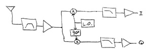
This means we will need a quadrature mixer which will produce two outputs
(I and Q) instead of the single (real) output provided by the RX320.
We still need to filter the RF signal to prevent images caused by mixing with
local oscillator harmonics.
We will also need to filter the IF output to prevent aliasing
if we are going to use the NI 6251 DAQ card as our A/D converter.
Here is a diagram of the required system:
Direct Conversion.
A
somewhat
simpler, all hardware solution
is the direct conversion receiver.
This can be gotten from the above system by simply eliminating
the lower branch of the mixer-IF chain and setting the local
oscillator frequency to 10 MHz rather then 10 MHz plus
(or minus) the chosen IF frequency.
Components: Options and Suggestions
- Connectors
-
If your circuit is going to mount on the Digital Radio Breadboard, the antenna
connector can be either a BNC or an SMB connector. If it is going to be a
stand alone system, it should have a BNC connector for the antenna.
In either case, the IF output connector should be a 1/8 in. stereo phone jack.
- RF Filter
-
Since we're mixing the RF input with a square wave local oscillator, signals near
harmonics of the local oscillator will also be shifted down to the intermediate frequency
if not filtered out.
Although a bandpass filter is shown, a lowpass filter would be adequate for this function.
If strong interfering signals at lower frequencies (e.g. AM broadcast stations
or the EMI in the lab) result in excessive dynamic range requirements, then a bandpass
filter may be appropriate.
- Amplification
-
The diagram shows both RF and IF amplification.
It is not necessary to use both in this application, as sufficient gain
should be obtainable in one stage.
So you could choose to use either an RF
or
an IF amplifier.
- Mixer
-
Since this is a fairly low frequency system, the best choice for the mixer is
probably a commutating mixer using CMOS switches.
Diode ring mixers require that the impedance at each of the three ports be
resistive (and of the same value) at all frequencies that may be present.
Since filters are typically reactive outside their passband,
(and since the RF signal must be divided between two separate mixers)
this requires fairly complicated circuitry for proper operation.
- IF Filter
-
Since the IF is at audio frequency, you could use either active or passive filtering
for the anti-aliasing filter. An active filter would have the advantage of not
requiring (relatively large value) inductors, and if you choose to provide the
necessary amplification at IF, could be combined with the IF amplifier.
Although the IF filter is shown as low-pass in the diagram, you should provide
appropriate blocking capacitors to eliminate the DC offset and
low frequency noise.
- Local Oscillator
-
During the initial prototyping, you should use the PTS-160 as your
local oscillator source, as was done with the transmitter in the previous exercise.
Once the signal path is working, you can replace the external LO with an on board
circuit.
If you're feeling adventurous, you could build an LC oscillator
or a frequency synthesizer.
However, since we only need to produce a single frequency, a programmable clock oscillator
would be a simpler choice.
- 90 degree Phase Shift
-
The transmitter circuit in last week's exercise uses a pair of D flip-flops
to convert a signal of 4 times the local oscillator frequency into a pair of
square waves of the appropriate frequency and phase. If you use a CMOS multiplexer
as your mixer, you can use a synchronous counter to divide a 4x clock
to produce address signals for the multiplexer.
Digital division provides accurately phased signals for any input frequency,
but since our receiver only has to work at one frequency, you could also
use RC or LC networks to achieve the required phase shift.
