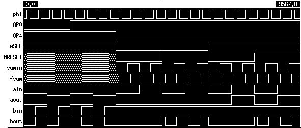
The various components of the arithmetic block were simulated individually and as a unit. In the case of each of the sub-units, an irsim command file was used to perform exhaustive tests exercising all possible inputs. After each of the sub-units was verified, the overall block was tested for several key cases to verify connectivity and performance.
The following tests were implemented through an irsim command file:

The simulation results above are also available in .ps format.
An irsim command file cycled the carry lookahead adder through all possible combinations of a and b input vectors twice: the first half of the simulation had a carry-in of 0, and the second half had a carry-in of 1. For each combination of inputs, the output (including carry-out) was observed for each possible combination of inputs.
The simulation results are available in .ps format in five sections: 1, 2, 3, 4, 5.
The output block was tested exhaustively with an irsim command file. ssum, the V2S1 feedback value, tracks sumin on ph2. sumout, the value passed to the output bus, tracks sumin only when ADDOUT is asserted (high). Otherwise, it is undefined.
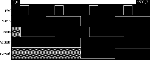
The simulation results above are also available in .ps format.
An irsim command file performed eight main tests on the fully assembled arithmetic block. Each of the diagrams below shows the values of the same set of signals:
Comments in the command file may be consulted to verify the output results.
During the first cycle, ADDOUT is deasserted and the arithmetic block is not driving the output bus. The value of o is undefined.
The following 16 cycles test the connectivity from the input bits to the output bits. Each bit of a is asserted in turn while b is held to zero, and vice versa. In each case, an 8-bit number with a single bit asserted is added to zero, and o contains the proper sum.
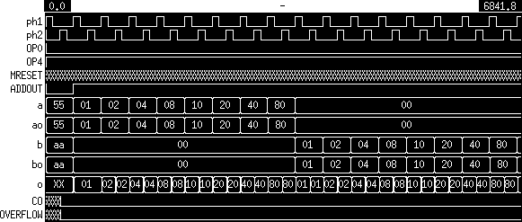
The simulation results above are also available in .ps format.
The first six cycles test standard addition with no expected overflow. The last five cycles test standard addition with expected overflow. Test cases include generating carries between the two 4-bit carry lookahead adders.
| cycle | a (hex) | b (hex) | o (hex) | CO | OVERFLOW |
|---|---|---|---|---|---|
| 1 | 00 | 33 | 33 | 0 | 0 |
| 2 | 6c | 00 | 6c | 0 | 0 |
| 3 | 55 | aa | ff | 0 | 0 |
| 4 | 3e | 03 | 41 | 0 | 0 |
| 5 | f8 | 88 | 80 | 1 | 0 |
| 6 | cc | 1f | eb | 0 | 0 |
| 7 | 55 | 55 | aa | 0 | 1 |
| 8 | 7e | 08 | 86 | 0 | 1 |
| 9 | 80 | ff | 7f | 1 | 1 |
| 10 | 80 | 80 | 00 | 1 | 1 |
| 11 | 7f | 01 | 80 | 0 | 1 |
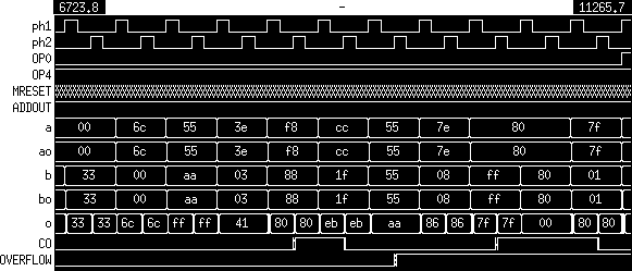
The simulation results above are also available in .ps format.
The first seven cases test standard subtraction with no expected overflow. The last four cases test standard subtraction with expected overflow.
| cycle | a (hex) | b (hex) | o (hex) | CO | OVERFLOW |
|---|---|---|---|---|---|
| 1 | 00 | 33 | cd | 0 | 0 |
| 2 | 6c | 00 | 6c | 1 | 0 |
| 3 | 55 | 55 | 00 | 1 | 0 |
| 4 | ff | 80 | 7f | 1 | 0 |
| 5 | 80 | ff | 81 | 0 | 0 |
| 6 | 7f | 01 | 7e | 1 | 0 |
| 7 | 01 | 7f | 82 | 0 | 0 |
| 8 | 80 | 01 | 7f | 1 | 1 |
| 9 | 7f | ff | 80 | 0 | 1 |
| 10 | 55 | aa | ab | 0 | 1 |
| 11 | ec | 70 | 7c | 1 | 1 |
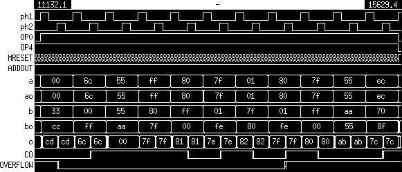
The simulation results above are also available in .ps format.
The above tests verified the connectivity and basic functionality of the arithmetic block. The following tests verify the internal feedback. The command file simulates the self-shifting b input register, and at each cycle we must observe the least significant bit (LSB) of the output vector and combine these bits with the final output.
| bin | hex | dec | |
|---|---|---|---|
| a | 11111111 | ff | 255 |
| b | 11111111 | ff | 255 |
| o | 1111111000000001 | fe01 | 65025 |
| cycle | o (hex) |
LSB of o |
accumulated output |
|---|---|---|---|
| 1 | ff | 1 | 1 |
| 2 | 7e | 0 | 01 |
| 3 | be | 0 | 001 |
| 4 | de | 0 | 0001 |
| 5 | ee | 0 | 00001 |
| 6 | f6 | 0 | 000001 |
| 7 | fa | 0 | 0000001 |
| 8 | fc | 0 | 00000001 |
| 9 | fe | 1111111000000001 |
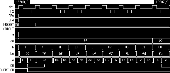
The simulation results above are also available in .ps format.
| bin | hex | dec | |
|---|---|---|---|
| a | 10001001 | 89 | 137 |
| b | 00101010 | 2a | 42 |
| o | 0001011001111010 | 167a | 5754 |
| cycle | o (hex) |
LSB of o |
accumulated output |
|---|---|---|---|
| 1 | 00 | 0 | 0 |
| 2 | 89 | 1 | 10 |
| 3 | 44 | 0 | 010 |
| 4 | ab | 1 | 1010 |
| 5 | 55 | 1 | 11010 |
| 6 | b3 | 1 | 111010 |
| 7 | 59 | 1 | 1111010 |
| 8 | 2c | 0 | 01111010 |
| 9 | 16 | 0001011001111010 |
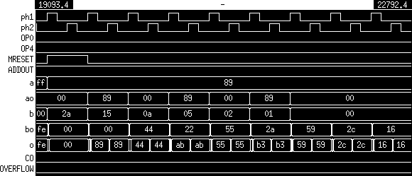
The simulation results above are also available in .ps format.