Previous Tutorial                 Main Menu                 Next Tutorial

Design Rule Checking


In this tutorial you are going to verify the inverter layout drawn in the previous tutorial using the Design Rule Checker (DRC). You should have basic understanding of the layout rules from lecture, but if you need a refresher, the links below will take you to the relevant section of the mosis web site. Be sure to use the SUBM version of the SCMOS SCN3M.

  1. nwell
  2. active
  3. select
  4. poly
  5. contact
  6. metal1
  7. via
  8. metal2
  9. via2
  10. metal3
For those who want to know all the layers, please go to this url.

Let's start verifying the layout we did in the last tutorial. 


Verify DRC

First of all, start cadence layout tools using "icfb". Bring out your inv layout view for editing. Refer to the beginning of the Layout Tutorial on how to open an existing cell view for editing.

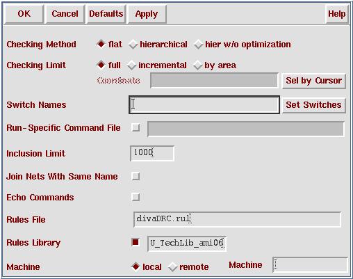
Now we are going to check if there are any DRC errors in the layout. The layout DRC rules are summarised by the design rules shown above. If you know what could be wrong in the layout, you can try to fix it/them and verify your modified layout by DRC. If not, let's go on to verification.

  1. From Virtuoso menu, select Verify -> DRC... This brings out a DRC from.
  2. Click "OK" on DRC form.


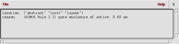
It takes a while to check all the DRC rules defined in the technology files. You can see those rules run across CIW very fast. After DRC checking is done, DRC errors will be highlighted in white on the Virtuoso Editing window. There is one error in this case. To see what the errors are

  1. From Virtuoso menu select Verify -> Maker -> Explain. Then click on the error. This bring out a marker text window with explanation. You can see the reason for DRC error is:


  2. Place cursor in Virtuoso window, press < Esc > to exit from maker explaination or File -> Close Window.

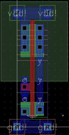
We have to fix the errors before we go any further. Press the F4 key to change the (F)Select:1 at the top center of the layout window to (P)Select:1 Now instead of selecting entire (full) shapes, you can select and adjust partial shapes. Select just the lower side of the poly. Move the mouse around until the cursor becomes an arrow pointing to a line. When this happens, you can left click and drag to adjust the shape of the rectangle. Make the poly region line up with the bottom of the larger nselect region

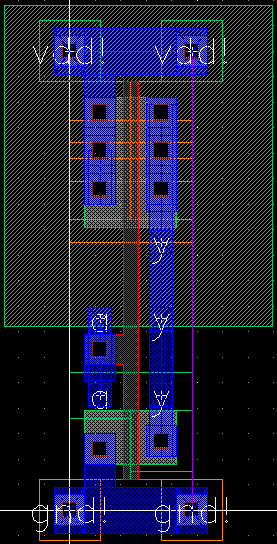
You need to do DRC again to make sure the error is fixed. You should find no error this time. Save your design before you go any further. Your layout view should look like this:


Print a Hardcopy

If you need a hardcopy of the layout, this is how you do it.
  1. If you wish to place rulers in your layout to show or measure lengths (in microns), from the Virtuoso menu select Misc -> Ruler k. Click on two points to place a ruler between them. (You can delete all rulers by typing shift-k)
  2. To plot, from Virtuoso menu select Design -> Plot -> Submit... A Submit Plot Form comes out.
  3. Make sure Library name, Cell Name and View Names are what you expect. Unselect Plot With "header" (This will save your printing quota). Click on "Plot Options". This brings out Plot Options form.
  4. In Plot Options form, turn on "Center Plot". Since you want to plot to a postscript file, turn on "Send Plot Only to File" and fill in "inv.ps".
  5. Comment: Plotting doesn't work well for Sun workstations. Therefore you need to plot to a postscript file first, then sent the postscript file to printer.

  6. Click "OK" on Plot Options form, then click "OK" on Submit Plot form. "inv.ps" should be located in the directory where you start Cadence. You may print it on any printer just as you print any postscript files.
You may close the inv layout view and quit Cadence now. 
Previous Tutorial                 Main Menu                 Next Tutorial