Previous Tutorial
Main Menu
Next Tutorial
Automatic Place and Route with Silicon Ensemble
When you are ready to automatically place and route your combinational
logic schematic, cadence requires a preparation step called PR Flatten.
PR Flatten should be performed on your highest level cell. It flattens
your hierarchical design to the level you specify. In our case we flatten it
to the lowest level standard cells.
autoLayout View
To perform PR Flatten, start Cadence using
"icfb". Then
- From CIW menu, select File -> Export -> PR
Flatten. A PRflatten form appears. Remember you should
perform PR Flatten only on your topmost level cell.
Note:If you did not
complete the adder in the schematic tutorial, you can string some inverters together on a schematic and use that as a practice design. Every cell in the design needs to have a layout and abstract view for this process to work.
- Type in your current library, cell name, and "schematic" as
View Name. Make sure Run is "Generate Physical Hierarchy
". Click "OK".
This will generate an "autoLayout" view for the combinational logic.
Open "autoLayout" view of adder for editing.
Comment: All the cells should be stacked with order inside the default
layout area. If you see overlapping, there might be something wrong with
your standard cells. The most common error is that you didn't set Cell
Type as "standard" for standard cells. Another possible cause
is having an improper routing grid in your design. Double check your basic
cells and if you choose to proceed, be wary or errors.
Export DEF
Now we can export the design to be routed. Click on File -> Export -> DEF...
Fill out the following form as appropriate
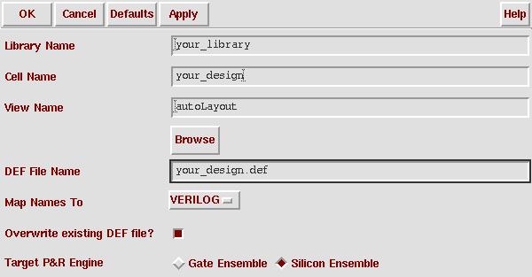
This will place a Design Exchange Format file in your cadence directory. This
file contains a list of subcells in the design and netlist information. You
can view it with a text editor if you choose. There are a few modifications that need to be made to this file before it will suceed in place-and-route. Some of those changes are performed by the perl script def_correction. This script strips out refereces to power and ground nets because they are routed differently than normal nets (usually through abutment).
Before you can import the design into Silicon Ensemble for place and route,
you need to have an abstract view that Silicon Ensemble can understand. Make
sure you have completed the previous tutorial on Silicon Ensemble's Abstract
generator.
Long Note: The abstract views created in the Abstract Generator
renamed the cells to ALL CAPS. Because Cadence is case sensitive, you will
need to go back and replace these capitalized names (in the LEF file exported
from Abstract Generator in the last tutorial) with the original,
lower-case cell names used in Virtuoso (and the DEF file created above). Otherwise, Silicon
Ensemble will not realize that the
inv specified in the DEF file is the same as the INV described
in the LEF file. The LEF names must agree exactly with those in the DEF file for SE place-and-route
to be able to find the cell. The only place the name file for a particular cell occur in the
LEF file are in the MACRO definition for that cell, found at the end of the file.
We've written a perl script which will edit the file for you called lef_corrections. Copy the script into the directory in which your cif
file resides and run it from the unix command line by typing
lef_corrections your_file_name.lef > new_file_name.lef
This will not change your old lef file, but will create a new one (new_file_name.lef) with
the appropriate corrections.
WARNING: The lef_corrections script assumes that all of you Virtuoso cell names
contain no UPPER CASE letters. If this is not true, you can either modify the script or manually
edit the file.
A shorter Note: Sometimes the origins of larger cells get shifted
in Silicon Ensemble. Make sure that the origin of each cell is (0,0), both when you perform
layout in Virtuoso (Edit -> Other -> Move Origin) and in the MACRO definition of the
cell in the LEF file (this is also corrected when you run the perl script lef_corrections).
Auto Routing
Silicon Ensemble is an auto-place and route tool by Cadence. It is designed
to place cells quickly and efficiently, but it has it's limitations. In concept
it's pretty simple:
-
load the design library (lef file from Abstract Generator)
- Load the design (def file from Virtuoso)
- Initialize the floorplan (cell dimensions, number of rows, ...)
- Place the I/O pins
- Place the Cells
- Route
... but it practice it takes a bit of tweaking to get everything to come out
well. It works best with low-level standard cells that strictly follow the
routing grid. Each cell must have a SITE associated with it of the same
type as the Row in which it will be placed. The floorplan automatically
makes all rows of the smallest-dimension SITE declared the the LEF file, which
is not always what you want. Abstract Generator also changes the name of every cell
to upper case, which is good for differentiating the SE and Virtuoso views in the
library (both have layout and abstract versions of the cells), but causes problems
when importing the design back into Virtuoso. It is important to go through the LEF file
and change all the cell names back to lower case (in the MACROS section of the file) so
that the cells specified in the DEF file are the same as those described in the LEF file.
In Silicon Ensemble
- Open Silicon Ensemble (by typing in "seultra" or "seultra -m=120")
in your design-specific directory. seultra -m=120 gives you more
memory if you need it (120 Megabytes).
- File->import->LEF, to import the file you just created in the Abstract Generator.
- Import your design by going to file->import->def (this is where you run into problems if the cells names in the LEF and DEF files have different capitalization
- Floorplan-Initialize Floorplan. Use the help button for more information
on each parameter. Select "Flip Every Other Row," which will put your vdd's
and gnd's together. I/O to core distance describes the distance between the external
pins and the core of the design. Use 0um to force all of the routing to stay inside
the cell boudaries or a higher value to allow external routing and more space for pins.
Row Utilization indicates how densely SE will pack each row -
higher numbers give you more dense designs, but smaller numbers will make it routing faster.
Calculate estimates the number or rows required to place the entire design and the
percentage of core area utilization (should be less that 100%). Play around with applying
different parameter values and see what it does to the floorplan.
- Place-IOs. Probably OK to choose random placement, unless you have some
special placement needs. If you do have special placement needs, next to I/O
Constraint File choose Write (unless you already have a file) to get
the correct outline and then choose Edit and modify as appropriate. Now
have the I/O Constrain File option chosen and click okay.
- Place-Cells. Just use the defaults and hit OK. It should now lay out your
design for you. If it does not suceed (most likely due to * Impossible to
place without overlaps!) try increasing the size of the floorplan or rows
(Either Floorplan -> Resize (or Stretch) Floorplan or click the
SL (and VS) column next to Row (upper left) and select
and drag the row to stretch it.
This is where you may get an error message
relating to power and ground nets if you did not edit the DEF file or run the def_correction
script.
- Place-Filler Cells-Add Cells. This fills out the space in your rows. The
model is "fill" or "fill2" and you can give it whatever prefix you want, like "f1."
Hit OK, and it should fill in the extra space for you.
- Route-Plan Power-Add Rings. (Note: You can skip this step for simple standard cell designs,
as gnd! and vdd! rails will naturally abut.) Change the core ring width and block ring width
to be a multiple of the your feature size, like 3.6 um. (For both horizontal
and vertical.) Hit OK. This puts down your power rings.
- Route-Connect Ring. You generally won't have to change the default settings,
so just hit OK. This should connect the power rings to your design.
- Route-WRoute. Make sure the "global and final route" option is
selected. This may take some time to process. When it is done, if there are turquoise
X's on sections of the design, it means that there is a geometry violation
(possibly a short). Check these section carefully and adjust if necessary (i.e.
try different floorplan, row utilization, pin placement, ...).
SE often runs out of memory and
crashed if you do too much after routing. When you have a cell you are happy with,
export it right away.
- File-Export-DEF...
In Virtuoso Layout Editor
- In the main "icfb" window, File-Import-DEF...
- Open the layout view of the file you imported and switch to the layout tool
- Click on Edit -> Search
- In the Search form, search for inst in current cellview,
with view name = abstract.
Replace with view name -> layout.
- Click on add criteria then choose view name criteria)
- Click on Apply, then Replace All.
- Close the search form, then click on Design -> Save as
- Save the design in the same library and cell, but change the view to
layout.
- Run a DRC check to make sure that the autorouter did not intoduce any
layout errors, and correct errors if necessary.
Note: If things start acting crazy, it's a good idea to exit SEultra and restart
it. This seems to take care of a lot of problems.
Previous Tutorial
Main Menu
Next Tutorial