 Shift! That's
one overrated actor if I've ever heard of one. His movie was the first to
crossover, he still has an acting career (but only in bad movies like
From Dusk To Dawn), and he got all the women. His soundtrack even got
an Academy Award -- what, is Oscar too good for Curtis
Mayes? No, wait, that's Shaft! Shift is one of my
favorite ALU units. Never mind -- just keep reading.
Shift! That's
one overrated actor if I've ever heard of one. His movie was the first to
crossover, he still has an acting career (but only in bad movies like
From Dusk To Dawn), and he got all the women. His soundtrack even got
an Academy Award -- what, is Oscar too good for Curtis
Mayes? No, wait, that's Shaft! Shift is one of my
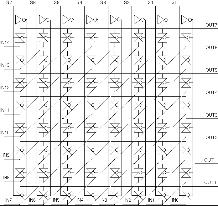
favorite ALU units. Never mind -- just keep reading.The shift unit conists of three parts:

| Type | D14 | D13 | D12 | D11 | D10 | D9 | D8 | D7 | D6 | D5 | D4 | D3 | D2 | D1 | D0 | Flip S? |
|---|---|---|---|---|---|---|---|---|---|---|---|---|---|---|---|---|
| SL0 | A7 | A6 | A5 | A4 | A3 | A2 | A1 | A0 | 0 | 0 | 0 | 0 | 0 | 0 | 0 | Yes |
| SL1 | A7 | A6 | A5 | A4 | A3 | A2 | A1 | A0 | 1 | 1 | 1 | 1 | 1 | 1 | 1 | Yes |
| RL | A7 | A6 | A5 | A4 | A3 | A2 | A1 | A0 | A7 | A6 | A5 | A4 | A3 | A2 | A1 | Yes |
| RR | A6 | A5 | A4 | A3 | A2 | A1 | A0 | A7 | A6 | A5 | A4 | A3 | A2 | A1 | A0 | No |
| ASR | A7 | A7 | A7 | A7 | A7 | A7 | A7 | A7 | A6 | A5 | A4 | A3 | A2 | A1 | A0 | No |
| SR0 | 0 | 0 | 0 | 0 | 0 | 0 | 0 | A7 | A6 | A5 | A4 | A3 | A2 | A1 | A0 | No |
| SR1 | 1 | 1 | 1 | 1 | 1 | 1 | 1 | A7 | A6 | A5 | A4 | A3 | A2 | A1 | A0 | No |
We therefore split the D inputs into three classes: D14-D8, D7, and D6-D0. In the first class, each D input can have up to five possible values (two constant). In the second class, D7 can have two possible values, whereas in the third class, each D input can have four possible values (two constant). Thus, we can use smaller multiplexers for each input. These multiplexers are described in greater detail in the circuit layout section.