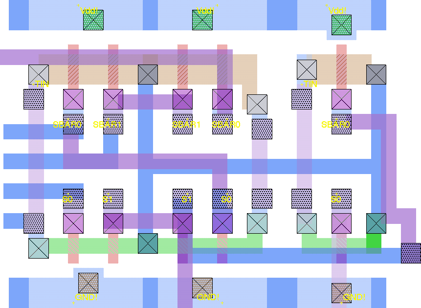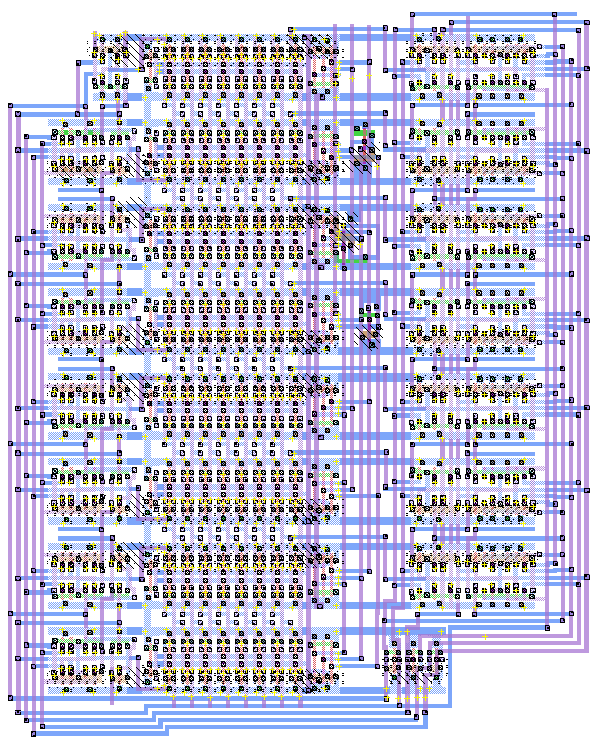


Shifter Inputs
As described in the circuit description,
the shifter select inputs can be implemented in a variety of ways. The
first and most obvious is by attaching a 7-to-1 mux on each D input of the barrel
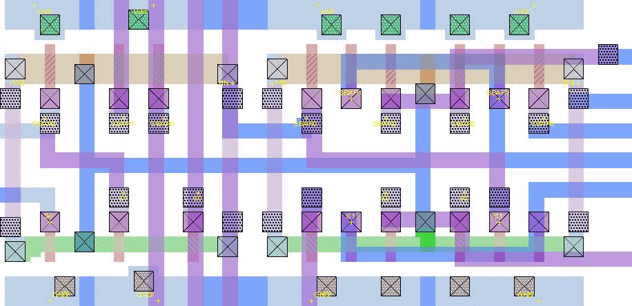
shifter in order to choose which shift operation to use. Such a multiplexer
would look like this:
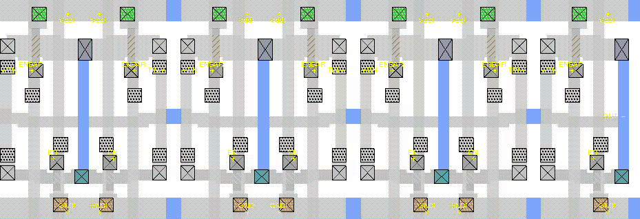
One advantage of this layout is that the appropriate select input can be wired straight through vertically. The select inputs for these muxes represent the specific shift-type operation above being used. However, this layout consumes a great deal of horizontal space. We see two obvious deficiencies in this layout. First, this layout does not exploit the similarities in the input patterns for each of the D inputs. Second, the opcodes must be decoded separately and then routed to the select inputs of these muxes.
To handle the first problem, we first split the D inputs into three classes: D14-D8, D7, and D6-D0. In the first class, each D input can have up to five possible values (two constant). In the second class, D7 can have two possible values, whereas in the third class, each D input can have four possible values (two constant). Thus, we can use smaller muxes for each input.
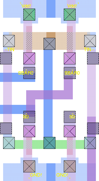
To handle the second problem, we use a circuit called the "anding-transmission-gate," shown below. If all select inputs are asserted, this gate acts as a short; if even one select input is not asserted, this gate is an open circuit.
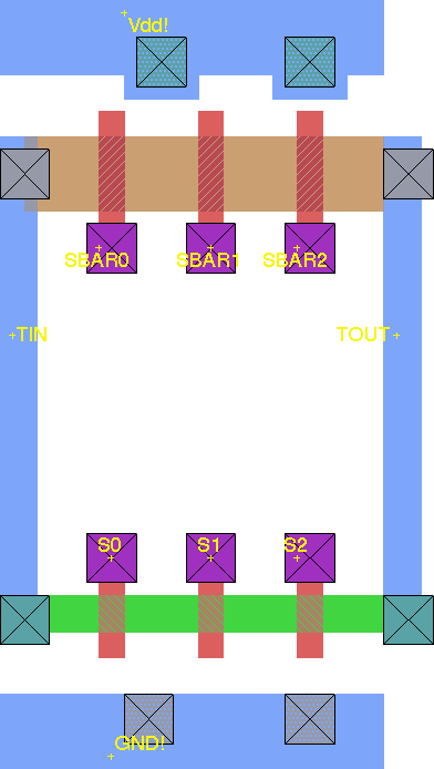
We use these anding transmission gates to decode the 3-bit shift opcode in each mux. We can thus optimize by using only the level of anding needed (for example, if all left shifts take the same value, that mux can be based simply on the first bit of the shift opcode). We can further optimize out the constant cases by making the constant value one of the opcode bits, rather than a hardwired data input to some anding transmission gate.
As a result, we have three different types of glue logic, based on the class of D input.
D14-D8
D7
D6-D0
