Previous Tutorial
Main Menu
Next Tutorial
Schematic Design Entry with Composer
This tutorial covers schematic design entry using a
2-bit adder
as an example. It assumes that you have finished developing the following low
level library cells: 2-input xor, inverter, and 2 and 3 input nand gates.
Start cadence using "icfb".
Placing Instances on schematics
Open a library cell "adder2bit" with "schematic" view in your
design library to store the schematic.
- File -> New -> Cellview
- Select "Composer-schematic" for Tools
The first procedure in design entry is importing library cells as
components into the design. To add inverters:
- From Composer-Schematic menu, select Add ->
Component ... i This brings out Add Component form.
- Fill in your library name, "inv" as
Cell Name, "symbol" as View Name and "inv1 inv2
" as Instance Names.
- Move cursor to the schematic window. You will see an instance image
moving with the cursor. This is inv1. Click left on a proper spot
to place it.
- As moving the cursor in schematic window, you will see another
instance image moving with the cursor. This is inv2. Click left on
a proper spot to place it.
You might need to zoom out the schematic window in order to put some more
component in it. Select Window -> "Zoom Out By 2".
To create "nand1" to "nand7", change
Cell Name to the name of your 2-input nand, fill in "nand1 nand2
nand3 nand4 nand5 nand6" as
Instance Names, and click left to place. Mimic the same action to
create "nand7" from your 3-input nand, and "xor"
from your 2-input xor. Finally,
press < Esc> to exit Create Instance.
You can move any instance by pressing and holding the left mouse button on it,
dragging it to the destination. Make sure you are moving the instance, not the
texts in it. If you do something wrong, select Edit -> Undo
to undo it. Refer to 2-bit adder to see where
to put the instances.
Connecting Wires
After the instances are created and placed, you can connect them with wires to
form the adder. To create a wire
- From Composer menu, select Add -> Wire (narrow)...
w
- Click left on the starting point, click left on as many transition
points as you want, then double click left to end the wire.
Then we need to create pins for input and output nodes. To do this
- From Composer menu, select Add -> Pin ... p An
Add Pin form appears.
- Type in "A B C carry sum" as Pin Names. Make sure the
Direction is "input".
- Move cursor to schematic window. Then click left to place pin
"A", "B", and then "C".
- Move cursor back to Add Pin form, change
Direction to "output". Then move cursor to the window, click
to place "carry" and "sum".
Remember to connect pins to the schematic with wires. Then the design entry is
done. Save your design by selecting Design -> Check and
Save.
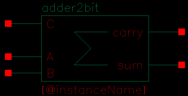
Generating Symbol View
If you want to use cell 'adder2bit' as components in other design,
you need to generate a symbol view for it. To do this
- From schematic menu, select Design -> Create
Cellview -> From Cellview ... This brings out a Cellview
From Cellview form.
- Make sure Library Name is your design library, Cell Name
is "adder2bit", From View Name is "schematic", To
View Name is "symbol". Select "Display Cellview" and
unselect "Edit Options". Click "OK".
A symbol view will be generated for this combinational logic according to
its schematic view. Then the symbol view will be opened for you. After
examining the symbol view, you may modify and close it, then save and close the
schematic view.

For more information about schematic design entry, refer to 'Composer Design
Entry User Guide'.
You may quit Cadence now.
Previous Tutorial
Main Menu
Next Tutorial

